 This week I had the hardest of tasks applying the texture to the model. The process is very long and complicated especially if the model isn't perfect.
To create the texture you use the original photos that were used in the beginning as references. You can create a texture map in 3Ds Max that can be imported into Photoshop to use as a painting template.
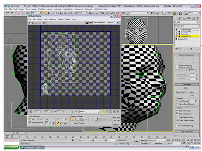
To produce the texture map you first have to apply a unwrap UVW modifier to the original half of the model. You only want the outer edges selected and leave the ear. The selected edges are highlighted in green. By using the cylindrical gizmo we can determine the path of the texture. The gizmo can be found in the right hand tool bar.
The image below shows the result of the unwrap UVW modifier. When clicking edit in the tool bar this window opens. It displays a flattened map of the model which was selected. Repeat the process again for the ear so that you have a separate map.
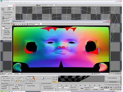
 Alterations can be made to the map in this window. Points on the map can be adjusted to avoid complications such as overlapping. You get the whole face map adding another unwrap UVW modifier above the models symmetry modifier. If you click on the model until the opposite side is selected, you can then simply select the mirror option in the edit window to get the other half of the face map. The two sides are joined by welding all of the points that run down the centre of both sides.
The image below is a quick render you can run that represents the shading on the model. The red areas show where parts of the map have overlapped. This can be corrected but the areas can affect the final texture.
 The image below shows my final texture map ready for painting in Photoshop. The ears are in the bottom left and right corners. Areas have been left open for the eyes and ears.
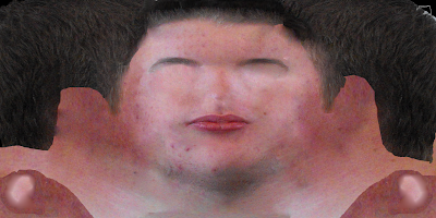
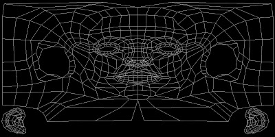 To create the texture I used the original photos and cut parts of the face away and placed them in accordance with the texture map. I kept saving the texture map so that it updated in 3Ds Max. This helped me to judge my progress. The image below shows the texture at a very early stage of development.
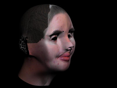
Final Map
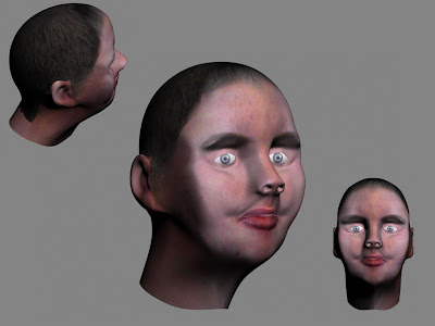
This is what my texture map looks like completed. I used the clone stamp and patch tools in Photoshop to blend the different areas of the face. The tools allowed me to generate an organic looking skin texture. The gaps that were left for the nostrils, eyes and ears were all covered with a skin texture to ensure the whole model was textured.
Conclusion
Overall I am very happy with what I have accomplished, considering this is my first attempt at modelling a head. Saying this, there are definatly things that I would change if I had more time.
The bigest change I would make would be to create the model using less polygons. The model I made had a lot of polygons which made it very complicated to manipulate without causing problems. It is because of this that the texture map wasn't perfect. I had too many overlapping faces which meant certain parts of the map didn't correspond properly with the model.
It has been a good learning expereince and I have picked up a few new modelling techniques along the way. I look foward to having another go at it when we are required to produce a charecter model.
 This image shows the results of the added polygons. I have also added a Turbo smooth modifier to give me an idea of the final result.

 This week I visited the Museum of Power in
 As you can see from this image i still have quite a lot of work to do. I want to try and smooth out the cheek area where some dips have appeared. The original mesh was created using spline modelling. The quads from the reference plate were traced using the line tool. Once the quads were created I then converted them all to editable poly's. In vector mode I pulled out each point of the shape to the desired position using the side reference plate as a guide. I have applied a mesh smooth modifier temporarily so I can see the areas that need improving.