Tuesday 8 December 2009

Week 12


The animation was finally completed this week. The final animation shows the engine appear from a cutaway model of a Mk14 Spitfire. The engine then rotates to reveal the pistons. As a finishing touch for the animation we decided to add some narration. It was my job to come up with the script. It is very difficult to write a script in a museum situation because of the varied audience. I did not want to make the script to complex but it needed to be informative.

The recording of the sound was very simple and all components were put together using Premiere Video editing software. With the animation complete all that we needed to do was to prepare for the presentation.

Evaluation

I am very happy with my contribution to this task. The Griffon engine is probably the most detailed and complicated model I have created to date. I wanted to set myself a challenge and I feel that I have succeeded. I believe that everyone in the group made some contribution to the product.

The presentation of the animation went well, and the guests from the Museum of Power seemed fairly impressed with the idea. They did have a few criticisms about the length of the animation and the content of the narration. These are both things that can be easily modified.

Overall I feel that this module has helped me grow in confidence with using 3Ds Max. I now feel I have the knowledge to tackle more complex models. I have also gained more experience working with and presenting to a client.

Week 11

This week was much the same as week ten. We sat down to watch the latest render of the animation, only to find that there was another problem with the way in which the pistons were animated. Again the solution was simple but we would need to render the whole thing again. This time around it was the first piston in the sequence that was running out of sinc with the rest of the pistons. At first I felt that the timing of the piston was not as bad as we first thought. Being the perfectionists that we are we still decided to re-animate the scene. It was later that Sav found that one of the Bones in the piston animation was bending, causing the delay in timing.

With the final presentation looming we knew this had to be the last time we could render the sequence. With the repair of the animation complete the only other addition to the final render was a new clay texture that shows a faint wire frame throughout the model. This will add to the technical/ mechanical theme we tried to achieve.

Between now and week twelve it is up to the group as individuals to decide what they would like to present to the client. I personally would like to start by talking about the reasons for choosing the Griffon engine. I will then briefly explain the methods invloved in modelling the engine and how I managed my activity throughout the project.

Week 10

This week Sav had a finished animation of the pistons moving inside the engine. At first we were all very impressed with how the animation had rendered. After much closer inspection we started to realise that the last piston in the sequence was jamming. It didn't take long for Sav to realise the problem and we came up with a solution. The reason for the piston jamming was down to the fact that it was the only piston in the sequence that had not been animated to loop once finished. In essence the problem was simple to solve but because of the large amount of frames per second we knew it was going to take a long time to complete.
We overcome the large rendering time by splitting the animation into five sections and rendered them accross five computers. This still took one - two hours per section to render.

The biggest factors effecting the render time were our choice of lighting, the use of reflective materials and the actual renderer we used. We used Mental ray lighting and used the Mental ray renderer to produce uncrompressed 'avi' files . We chose to render the scene as an uncompressed file so as not to lose any quality when importing the video sections into the video editing software.

We also found that when the scene was rendered all of the materials which I had applied to the engine previously had been white washed. The material properties still remained but there was no colour other than white. This down to the settings that had been applied during the lighting process. Although this happened by mistake, we all liked the simplicity of the colour scheme. With everything rendered white we found that textures did not take away from what we actually wanted to show- the pistons.

At this point in the production process it became apparent to us that the more we added to the animation the more complicated and time consuming it became. We calculated that if we used the environment that the render time would take around thirty hours. This wouldn't be possible on the timescale we were working on. The extra modelling would also mean that the file size of the animation would double, meaning it would take up a lot of space on the clients computer.

Further cuts from the animation could include the Spitfire model. We feel that taking these aspects out of the animation will not damage the message we are trying to portray. Without these aspects we can allow for a higher error of margin. If we need to repeatedly render the scene it will take suggnificantly less time than we originally anticipated.

As it stands the animation consists of the engine rotating with one of the piston blocks as a wireframe. Inside the wire frame the pistons have been animated using bones to simulate the linear motion.

Week 9

I started week nine by modelling a part of the engine called the Magneto. This was very simple to create as only used generic shapes. I used two box's, two cylinders and a rounded box. After creating and scaling the shapes I positioned them accordingly and then grouped them.

With the fairly easy task of creating the Magneto finished I moved on to producing the pipe work and wires for the whole engine. To create the pipes and spark leads I used the line tool. When drawing a line you have a variety of options. I chose to draw my lines smooth with smooth corners. In the line drawing window there is also a drop down menu labelled rendering. If you enable the box that says 'Render in viewpoint' you can set a line thickness. This is how I achieved the complex shape and bend on all of the wires. I varied the thickness depending on the application of the wire or tube. I could have used cylinders and modified them but this way is simpler and more effective.

Gear Housings

I modelled the lower gear housing from a cylinder and half of a sphere which I squashed using the scale tool. The two parts were scaled in relation to the rest of the engine. The other two gear housings were simply created using squashed capsule shapes.

Detailing

To give the model a more realistic feel I decided to add some detail in the form of rivets and bolts. The bolts on the head cover are made up of tiny cylinders. There are thirty-two on each cover. The rivets are made up of spheres. These are used on the crankshaft casing and lower gear casing.
There is a mix of fittings on the main gear housing. The bolts around the outer edge are modified cylinders. These have been modified to look like a two part bolt. Around the inner edge of the gear housing I have used tube shapes to simulate open screw holes.

Another addition to the model was the six exhaust ports on each piston block. These were created from modified boxes. I used Boolean to cut out the centres.

I also added the Rolls-Royce wording using the text tool. After writing out the words I used extrude to give the lettering depth and applied it to the covers.

With the model completed to a respectable standard I decided to start adding textures and materials. I wanted to keep the main parts of the engine matt and the top covers were to be chrome.

The hardest material that I had to create was the chrome needed for the head covers. I followed the basic principles from a couple of tutorials which I had read. To start with I opened the materials editor and with new material selected I set the diffuse colour to a dark grey. This acts as the base colour.
The next thing I did was to go into the maps pull down and assigned 'Raytrace' in the Reflection bar. By doing this the material reflects other objects and the environment in the animation.
When returning to the parent material panel I adjusted the specular and glossiness levels to suite the animation. The adjustment of these levels depends on what environment and lighting is being used.
With the other metalic textures on the model I decided just to use bitmaps and alter the specular and glossiness levels to give a shine and reflection.

The braided texture on the two front hoses is made from a bitmap which I sourced. To add extra depth I added a Bump Map in the Map pull down. All I did was to assign the original bitmap into the Bump Map bar. This gives the material extra depth by exagerating the darkened areas. The lighter areas of the bitmap will appear raised. On the model I created this gives the raised woven effect of the braided hoses.

All of the materials and textures which consisted of a Bitmap image were scaled using the UVW Map tool in the modifier pull down. When clicking on the UVW Map you are given an option of 'Gizmo' which once selected allows you to alter and manipulate the texture on a chosen object.


Week 8

This week I created the other half of the 'V' engine by Mirroring my initial model of the piston block. To do this I simply selected both part of the model and made a copy of them. These copies were then mirrored by adding a Mirror modifier from the modifier panel. All that I had to do after this was to position the mirrored copies on the opposing side of the engine body.

In addition to the body of the engine which I started last week I added another box shape towards the front of the engine. After raising the polygon count I converted this box into a editable poly. I picked points in vertex mode to create a half cylinder shape from the bottom of the box. Once happy with this I added a mesh smooth modifier to round off all the sharp edges. The Smooth modifier makes the shape look more organic and realistic.


In the second half of the week I continued with the model by creating the visible section of the crankshaft and its housing. This part of the engine is very detailed and I wanted to be able to spend a fair amount of time getting the shapes and modelling fairly accurate. The starting shapes of this part of the model were: three cones, a cylinder and a tube.

I started with the biggest part of the setup. This is where all of the gears that drive the crankshaft are housed. The basic shape is a cone, but I have altered it by raising the polygon count and applying and edit poly modifier. By selecting the faces on the underside of the cone I was able to create a bulge below the main housing. I had to make sure to retain symmetry whilst modelling this section. This shape that I created was effective in itself so I left the modelling there and applied a smooth modifier.

The rest of the shapes remain virtually un-touched, but for a few tweaks on the other two cone shapes. These were altered slightly using an edit poly modifier.

Week 7


This week I continued with the modelling of the engine block. From the reference photos I could see that there was a set of indentations that ran vertically along the length of the block. To create these indentations I used the Boolean tool.
First I created a cylinder that was the same height as the block. It was important that the indentations would be to the same scale as the existing block. As I was not working with specific dimensions a lot of the model relies on my instinct.
With the shape scaled I then copied the shape another six times. Once the cylinders were evenly spaced I opened the Compound objects window and selected Boolean. As I wanted the cylinder shapes subtracted from the block I needed to have the block selected. With the shape selected you can then click the button 'Pick Operand B' and click on one of the cylinder shapes to subtract one shape from another. This was repeated for every cylinder.

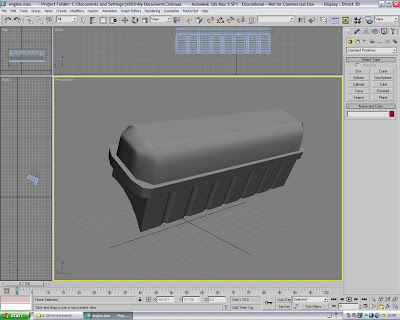
With the first side of the engine block completed I moved onto modelling the Head cover. This again started with a box shape. I altered the the number of polygons in the modify panel to make it easier to model. I then converted the shape to an editable poly and proceeded to alter the shape in vertex mode. I altered points on the top of the shape to achieve a domed/ smooth shape. I also selected a row faces around the bottom of the shape and extruded them to create a lip around the edge.

Once the block and head cover were complete I applied a shell modifier to both pieces to achieve the hollow shape. I grouped the shapes and rotated them to create one side of the 'V'.

To imatate the bulk of the engine I used two cylinders and a box. I will add to this later but this will give me the basic shape to add too.

Week 6

With the model of my face/head now complete I can concentrate on the Museum of Power brief. The group as a whole have decided to go with the idea of modelling and animating the movement of pistons in a V12 aero engine. It was suggested by one of the group that we base the model on the Rolls-Royce Griffon engine.
The inspiration for the idea comes from the Rolls-Royce 'R' racing engine that the museum has on display. The engine on display and the engine we will model have very similar principles. We chose to use the Griffon engine because of its historical importance. When researching the idea we found that the Griffon was the last V12 aero engine of its kind to be produced by Rolls-Royce Limited.

At the start of the project I was assigned the task of creating a sky texture to be used as an environment for the animation. I was happy to do this but felt i needed more of a challenge. After further discussions it was decided that I was to model the Griffon engine.

The tasks assigned to other group members were:
  • Martin- Overall Environment
  • Richard- Environment details (Including buildings)
  • Savva- Spitfire and Piston animation

To start with I only had one image that I could use as a reference for modelling. I have a basic knowledge of mechanics so I knew what I was looking at, but I wanted to get the overall shape as close to the real thing as possible. After searching the internet for more images and information I began modelling the first part of the engine.

I started by modelling one side of the engine block where the first six pistons will be housed. To start off with I used a simple box shape as the actual shape is quite linear. As the two sides are simetrical I can create one side and mirror it to save time.

Wednesday 21 October 2009

Week 5 - Dreaded Textures

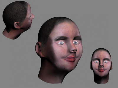
This week I had the hardest of tasks applying the texture to the model. The process is very long and complicated especially if the model isn't perfect.

To create the texture you use the original photos that were used in the beginning as references. You can create a texture map in 3Ds Max that can be imported into Photoshop to use as a painting template.

To produce the texture map you first have to apply a unwrap UVW modifier to the original half of the model. You only want the outer edges selected and leave the ear. The selected edges are highlighted in green. By using the cylindrical gizmo we can determine the path of the texture. The gizmo can be found in the right hand tool bar.

The image below shows the result of the unwrap UVW modifier. When clicking edit in the tool bar this window opens. It displays a flattened map of the model which was selected. Repeat the process again for the ear so that you have a separate map.

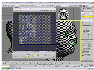
Alterations can be made to the map in this window. Points on the map can be adjusted to avoid complications such as overlapping. You get the whole face map adding another unwrap UVW modifier above the models symmetry modifier. If you click on the model until the opposite side is selected, you can then simply select the mirror option in the edit window to get the other half of the face map. The two sides are joined by welding all of the points that run down the centre of both sides.

The image below is a quick render you can run that represents the shading on the model. The red areas show where parts of the map have overlapped. This can be corrected but the areas can affect the final texture.

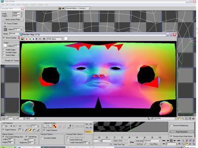
The image below shows my final texture map ready for painting in Photoshop. The ears are in the bottom left and right corners. Areas have been left open for the eyes and ears.

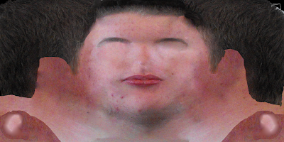
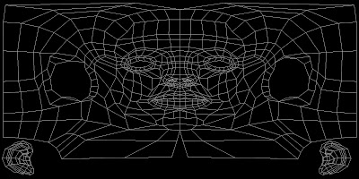
To create the texture I used the original photos and cut parts of the face away and placed them in accordance with the texture map. I kept saving the texture map so that it updated in 3Ds Max. This helped me to judge my progress. The image below shows the texture at a very early stage of development.


Final Map


This is what my texture map looks like completed. I used the clone stamp and patch tools in Photoshop to blend the different areas of the face. The tools allowed me to generate an organic looking skin texture. The gaps that were left for the nostrils, eyes and ears were all covered with a skin texture to ensure the whole model was textured.


Conclusion

Overall I am very happy with what I have accomplished, considering this is my first attempt at modelling a head. Saying this, there are definatly things that I would change if I had more time.

The bigest change I would make would be to create the model using less polygons. The model I made had a lot of polygons which made it very complicated to manipulate without causing problems. It is because of this that the texture map wasn't perfect. I had too many overlapping faces which meant certain parts of the map didn't correspond properly with the model.

It has been a good learning expereince and I have picked up a few new modelling techniques along the way. I look foward to having another go at it when we are required to produce a charecter model.

Week 4 Features - Mouth, Eye lids, Nostrils and ears!!!

This week I continued with the face by adding extra polygons for the mouth, eye lids and the inside of the nostril. At first I thought this would be very complicated but after watching the tutorial I was able to complete the task within an hour.

To create additional polygons I used a simple drag and copy method. Using the edge select option in edit poly, select an edge you want to add too and drag it out whilst holding down shift. This will create an additional polygon that is already attached to the starting edge. I repeated this until I had all the new polygons I needed.


If you have two new polygons next to each other they are joined to the original selected edge but they are not connected to each other. To connect them you switch back into vertex mode so that you can see all of the points on the model. Then in the side bar, select target weld and click a top vertex on one of the polygons. A dotted line will appear from the selected point as a reminder of which vertex has been selected. If you now click on the nearest top vertex on the next polygon the points will merge/weld. These points will now be joined. Test the weld by moving the vertex and seeing if the two polygons alter simultaneously.

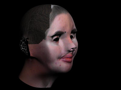
This image shows the results of the added polygons. I have also added a Turbo smooth modifier to give me an idea of the final result.

Ears

The ears were developed in the same way that I made the head. After producing a topology map for the ear I switched the properties of the model of the head to hidden. I traced the topology with the line tool to create the polygons. With the polygons selected I converted them using an edit poly modifier and selected the weld button to join them.

As with the head I modelled the ear in vertex mode, pulling points out to produce the basic shape. I also used the press shift and select short cut to create more polygons to add depth to the model.

With the ear modelled I re-introduced the head model and cut a hole for the ear by deleting polygons. The two models were attached by clicking the attach tool an then all points were welded using the target weld tool. Parts of the model had pulled due to the lack of polygons around the ear area. Just by playing with some of the points I managed to reduce the stretch considerably.

Week 3 - Need to Blog!!!

Ive been so eager to get the model finished that I have been neglecting the blog for the last few weeks. I have accomplished quite a lot since my last blog and the model is very near completion. In this update I will carry on from where I left last time.

Symmetry

In my last blog I spoke about alterations I wanted to make to the early model. The cheek areas were very bumpy and a lot of the facial features were very sharp and didn't appear natural.

I made the alterations by using the edit poly tools. I feel the best selection to use is vertex as you can select specific points rather than large areas. Being a perfectionist I spent hours re-arranging points to try and get the face looking how I wanted. I got to a point where I felt the model had improved enough to progress to the next stage. I made this decision purely beacause of time constraints. Im sure I could have spent many more hours making tiny alterations but I needed to leave enough time to at least attempt some of the other tutorials.

The image above shows the results of the alterations i made. Compared to the original model I think it looks ten times better. I now have the full face after adding a symmetry modifier to the side i had already created. The modifier made a duplicate of the original as well as flipping it horizontally. I used the move tool to line the two sides up. The duplicate will update if i make any changesto the original model.

Tuesday 6 October 2009

Week 2

This week I visited the Museum of Power in Langford, Essex to gather some ideas for the group project. From first glance it appeared that the main focus of the museum was the large collection of Steam engines and pumps. After closer inspection i found that there were a lot of other interesting artifacts on display ranging from tools too cameras and even car and plane engines.

Looking at the steam pumps I could see that the mechanisms that drive the actual machines were very complicated. Any animation of such machines would need to be timed perfectly, which would be very difficult.

From what I had seen I felt that most of the exhibits would present some challenge to our group when we come to modelling our chosen idea. I would like the challenge of re-creating one of the smaller steam pumps but it depends on what the group as a whole decide to animate.


As well as the museum visit I have also progressed with the model of my face. After completing the line structure on my face and drawing the quads last week I now have the basic shape modeled and ready for tweaking.

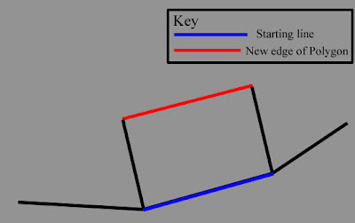
As you can see from this image i still have quite a lot of work to do. I want to try and smooth out the cheek area where some dips have appeared. The original mesh was created using spline modelling. The quads from the reference plate were traced using the line tool. Once the quads were created I then converted them all to editable poly's. In vector mode I pulled out each point of the shape to the desired position using the side reference plate as a guide. I have applied a mesh smooth modifier temporarily so I can see the areas that need improving.

Friday 25 September 2009

Week 1

The Brief

After looking at the brief for this module I can see that i have a big challenge ahead. For this module I will have to model and animate a model of my face and head.

I have watched three tutorials on the processes invloved in the preperation of this type of modelling. I can see from these that this model will be a lot more complicated than anything I have attempted before.
I will have to create the animation using Spline modelling techniques. I will use two reference pictures of my face and the side of my head. The pictures will have the details of my Topography drawn on to help me with the modelling process.


This image shows the two reference plates I have created with all of the relevant topology. I used Photshop to draw on the topology as well as dividing the topology to create the quads. I highlighted the quads using a red brush to give me a clear reference to work from.